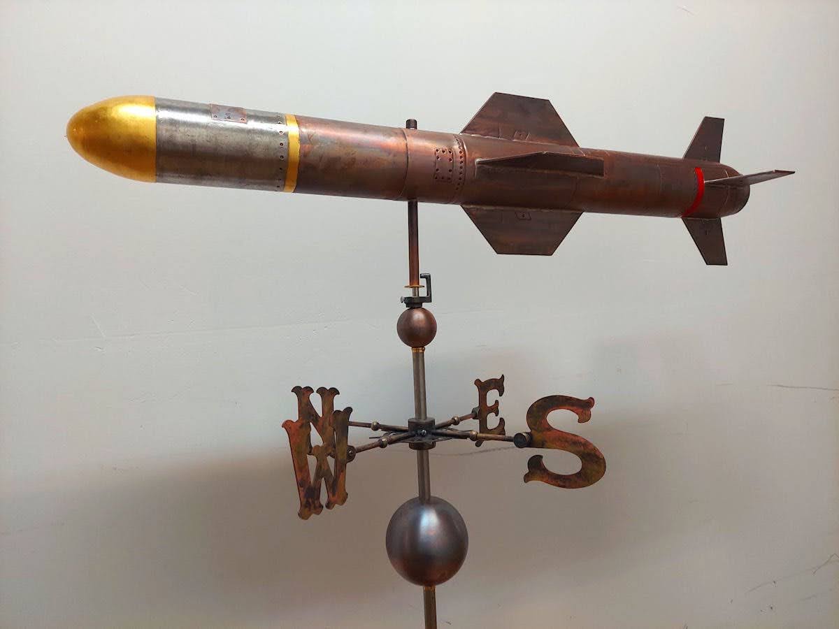
Two years after moving to Northern Virginia, I have finally put the finishing touches on my rocket barn. I’ll be publishing new updates, including all of the new goodies I’ve built and purchased for rocket building. Stay tuned!
Building Rockets for space in my barn

Two years after moving to Northern Virginia, I have finally put the finishing touches on my rocket barn. I’ll be publishing new updates, including all of the new goodies I’ve built and purchased for rocket building. Stay tuned!


Launched the “Airstream of Consciousness” yesterday at the Midwest Power XIII Rocket Launch in downstate Illinois. This was a hand made scratch built all-carbon fiber rocket using my filament winder for the airframe and a 10 ton press for the fins. Since Carbon Fiber attenuates (acts as an RF shield) my ham radio spectrum downlink, I used a traditional fiberglass nosecone and put the electronics there. I had 7 camera’s on the rocket! If you look closely, on the tip of the nosecone, I had a bubblcam. I was a kickstarter backer for this thing, it’s basically 4 video camera’s built into a spherical ball to take 360 video’s which can be played back on an oculus rift, Google cardboard, or on YouTube using a mouse. Unfortunately, the centripetal force on the camera due to the spin ejected the microsd card mid flight.
Video in all it’s glory:

The most common question I get from people who first find out I enjoy rocketry (after – “is it legal?”) is how the rockets are built, and what kind of tools do I use. I’ve recommended my own blog of course, but realized the level 3 build which started this blog didn’t discuss any tools, or core manufacturing techniques at all. So, this will be a short tour through my workshop.
First, what I’m not going to show you – the “base” of my workshop looks a lot like someone poured a mechanic’s garage into a woodworkers toolshed, and threw in some culinary equipment. Drill press, table saw, giant mixers, scroll saws, bench sanders, and lots of tools. Nothing really special here, and I’ve tended to go cheap (think Harbor Freight) on many items because I just don’t use them often
  enough to appreciate the difference. I guess the one tool in this area that is not found in your average garage is a TIG welder. There are some areas in rocketry in which there is no better alternative then metal, in my case, aluminum. Think motor cases, push rods, even fins. This is an alternate view of my 99 mm aluminum tig-welded fincan that fits perfectly over a 98 mm motor case, which I will be using as the booster section of a minimum diameter sounding rocket I am working on.
 The fun begins with equipment not often found in your typical shop. I build a lot of electronics for fun, including custom electronics for rocketry. While the boards themselves are milled on my cnc machine (which you’ll see in a bit), most of the fun is in my basement office, which happens to also
 be a good soldering bench. With the number of soldering guns and stations I own, you would think I’d be good at it by now, but I’m not. I’m like the baseball player that can’t hit the ball, but sure can run the bases. In this case, I often stumble in the original build, but I’ve gotten really good at reworking a board. In fact, my reflow and rework station equipment is professional grade including IR camera’s and a robotic arm to help my sausage fingers manage the tiny SMT bits and pieces being made today. One of my old hobbies was collecting vintage computers, which provided me hours and hours of electronics board repair training. At one point in my life, I was lucky enough to own an Apple 1, and successfully brought it back to life. I’ve also spent a week rebuilding the electronics in a McDonalds happy meal that stopped working, and brought my eldest daughter to tears……
Next up is a filament winder. This is a computer controlled machine which which allows me to make the rocket sustainers, and other parts out of any kind of filament. Think carbon fiber, fiberglass, Kevlar. basalt, etc. These highly specialized machines normally cost 50,000 to 100,000 dollars. An enterprising guy named Turner Hunt decided to try and make a hobby version, and launched a kickstarter . The first one didn’t go so well, but the second was successful. The entire machine is built with 8020 extruded aluminum, and the same stepper motors I use in 3d printing. The secret sauce is in the software, which can control the number of wraps, and the angle of each wind to create very specific circumferential, or longitudinal tensile strength.
I have done extensive development in openscad to allow me to model different winding angles and build the profile perfectly before even starting a part. In this video I am winding a 6” diameter carbon fiber sustainer, which you will see fly in a video later this year. You can see more videos of the filament winder on one of my YouTube channels.
My second favorite tool is my home made CNC machine. a CNC machine is basically a router, or spind
le bolted to a computer controlled gantry. I sure do love tools controlled by computers! In this case, I can build on my computer exactly what I want cut out in 3 dimensional space, then the CNC machine will do all the work to very, very tight tolerances. Makes things like fins, AV bays and centering rings trivial to make to exact specifications. What is really exciting about a CNC machine is it can go well beyond the basic building blocks, to build extremely complex parts. The x-15 build lower on the page c ould not have been built without a CNC machine. In this video, one of my daughter’s had designed her pinewood derby car on the computer, and we let the CNC machine do all of the work. Needless to say, she won first place in the “best design” category.
 While I’ve talked about 3d printing in a previous post, I should point out I now own 6 different 3d printers, each one getting bigger, and more complex. The “Zoghlin Aerospace” delta printer to the left can build objects over 12” in diameter, 3 feet high. In this photo, it’s building a 4” rocket with integrated fins, and all internal components except the electronics are integrated as it prints. printing the entire rocket at once allows you to build extremely detailed rockets that would be very time consuming, if not impossible using traditional techniques. In the photo b
 elow I was able to integrate a complete Dr. Who callbox into a rocket, and print out the entire rocket and flat nose cone at the same time. As you can see with the green rocke
 t, I can also create traditional rockets, and print out all of the parts at once. If you would like t0 see more, I have several rocketry related 3d prints available on my account thingiverse including
  modular 38 and 54mm rockets, rocket camera holders, and most of the parts for a complete Saturn V (photo of it completed is lower down on this page).
While I use a lot of 3d modeling software products including Inventor, Solidworks, Aspire, there are times when you just want to make a copy of something physical. I have three laser scanners, and a structure I/O device which allow me to take real objects and dynamically build models out of them. In the photos below, I scanned a statue of wife. The laser scanner interprets the statue as tens of thousands of points in space (called a pointcloud). I can then use this pointcloud to create a mesh, which ultimately creates a 3d model. The blue version is the finished 3d model, which looks exactly like the original statue. I’ve scanned lot’s of things, and once again you can find them on thingiverse if you have any interest.


Most of the laser scanners are like the my AIO robotics – a moving platform, and a scanning laser combine to create slices of an object. This works great for small objects, but when they start to get big, it becomes more and more expensive, not to mention the time to get a working model. The Structure I/O (object with a white cover on it) connects to my iPad, and uses the iPad camera, combined with it’s own depth sensors to build models in real time by just moving the iPad around an object. This allows me to get much larger objects, vehicles, people, architectural accents, etc. I scanned my youngest daughter with the structure I/O, then used the model to create a rocket noscone that looked exactly like her head. I scanned a Harpoon missle at the museum of science and industry, then used the dimensions to assist with the harpoon you see lower in the website.
My last major toy is a laser cutter. I don’t need to say much about this one, it’s a big freakin’ laser, controlled by my computer, that can cut almost anything. The version I have is an industrial one, I always keep an eye out for manufacturing equipment that looks like it’s being sold cheap on craigslist. In this case, I was able to get a commercial very large 100w laser with lot’s of accessories (liquid chiller, blower, exhaust system, auto-focus, red dot) for a fraction of the cost of even a low power hobby one.
I have other “toys” in the workshop, like a mini-mill and a 4th axis router, but they are just variations of the wonderful machines I’ve already highlighted. Finally, as I’ve become more proficient in the computer controlled machines, I’ve been able to branch out, and build similar machines that don’t go into my workshop, but are used by the family for other crafts. Below is my Christmas ornament maker. It’s a CNC machine for designing Christmas ornaments. Instead of a spindle, we just put a pen, and away it goes.They made great presents this year.


Sorry for the EXTREME delay between posts! Work has been getting the better of me. Given how much knowledge and equipment I’ve collected over the years to build rockets, I’ve found these skills are useful for building other fun electronic projects. I received my pilots license over twenty years ago, but let both the skills, and my license (my medical) lapse long ago. The bug bit me recently to freshen up, and I was amazed at what the state of the art in simulation looked like. Like rocketry, there is a small, but dedicated community of enthusiasts that have made some amazing amateur simulators. While I don’t exactly have the room for a full blown simulator, I was able to build a simulated cockpit panel, and mount it on a movable metal pole to refresh my piloting skills.

I also happened to build a few rockets too :> As soon as we have a warm weekend, I’ll take them out for a photo session. The most common question I get is what tools do I use to build all of these things. In the next installment, I’ll take you on a walk through my laboratory (My wife call is the garage) of CNC machines, laser cutters, filament winders, 3d printers, reflow stations, laser scanners, PCB etching equipment and random tools I use.

Finally launched the monster motor.
Rocket weighed over 150lbs on the pad. Apogee was at 14,375 ft, and landed about 1.5 miles from the launch site in a small forest. My eagle-eyed daughter saw the parachute caught at the top of the largest tree.
The name of the rocket is a shoutout to the hosts of a podcast called no agenda which can be found at http://www.noagendashow.com/ . The show should be required listening for the rocketry community – especially after the Bureau of Alcohol Tobacco and Firearms tried to shut down the hobby.

Talk about true love! Under our tree this year was a brand new six inch Gorilla Rocket motor, Reloads, Nozzle, and a kit to put it all together. Can’t wait to try it out. Looks like my first chance will be Thunderstruck 5 this spring in Indiana….. Thanks Deann! I love you.


 Had a great time at Tripoli Wisconsin’s launch today at the Richard Bong State Park (Bong to us local’s) just over the boarder in Wisconsin. Tim “Wildman” Lehr grilled the entire crowd
  free lunch! Work has kept me from most of the launches this year, so this was my first time launching from our new spot in parking lot “E”. The spot isn’t bad, except it’s right next to the bathrooms which limits our ability to launch anything larger than a K motor. Hopefully with the announcement of LDRS coming to Bong next year we will once again be able to use our primary spot in the middle of the park. The weather was absolutely beautiful and perfect for flying. I participated in the annual Minie
  Magg
Magg 
 drag race, even though I didn’t even know it was scheduled! One of my daughter’s liked the look of the rocket, so we brought it along. Unfortunately, I didn’t stick the landing
 ![]() . Parachute didn’t deploy, so I had to scrape the remains of the rocket off the side of the road. Also launched my scratch built Nike
. Parachute didn’t deploy, so I had to scrape the remains of the rocket off the side of the road. Also launched my scratch built Nike Smoke. Perfect Launch, but it went so high it landed in the back half of the park which is all swamp and lake. We never did find it
 ![]() . Kids had a blast launching from the low power pads. Tried several new rockets, including a few gliders with mixed results. One big lesson… don’t put an ammonium perchlorate based motor into a light glider. We spent quite a while picking up the shredded pieces across the flight line. My good buddy Aaron brought two of his boys up to watch as well. Always fun to see new kids get excited about the hobby.
. Kids had a blast launching from the low power pads. Tried several new rockets, including a few gliders with mixed results. One big lesson… don’t put an ammonium perchlorate based motor into a light glider. We spent quite a while picking up the shredded pieces across the flight line. My good buddy Aaron brought two of his boys up to watch as well. Always fun to see new kids get excited about the hobby.


Wow!
I can’t believe it’s been almost 6 months since my last update. I guess life has been getting in the way. I certainly haven’t given up on rockets – if anything, my other hobbies have been suffering at the expense of rocketry. Spent the winter building, and rebuilding several rockets. A 98mm carbon fiber minimum diameter rocket (Like my old Tachyon here), a Ultimate Wildman (a platform to test some video hardware), and a Saturn V. The Saturn V is about 1/35th scale – as you can see in the photo, it’s significantly larger then my Redstone at almost 11 feet tall. What makes this Saturn V interesting is many of the parts on the rocket were built using my 3d printer. I’m currently working on the 3d model for the Launch Escape Tower. You can download my model from thingiverse page here. Just a word of warning – while the model is finished, it’s not printing correctly. I may need to
  add a raft, and some supports to ensure the build works. The 3d printer itself is an absolute blast. I can’t tell you how much of my free time I’ve wasted. I recently acquired a nextengine 3d laser scanner which essentially allows me to laser scan any object, then print it on my printer. I’ve become my own bespoke reverse engineering manufacturing plant in my basement. You can see some of the 3d scan’s I’ve done on my thingiverse page linked above.

I can basically print an entire rocket ready to launch. This particular rocket is so light and strong (ABS plastic, extruded with a 15% fiill) it doesn’t need a parachute, or even a streamer.

Finally launched the Harpoon!
Flawless launch at Midwest Power 10. Only real issue is I lost the fairing that covered my Go Pro camera, but that was actually by design. I was really worried the fairing would collapse and I would loose any good video. I had read about making an Adruino motion sensing switch on a blog at the University of Illinois Engineering website (my Alma Mater) a few years back and thought it would make an interesting solution to my issue. I built a few prototypes, and eventually settled on a design that would blow the fairing off the rocket if a photosensor detected returning laser radiation over a specific threshold. In the video below, you can see the fairing collapse right at 1:55), the Go Pro picking up the laser dot, then shortly afterward, the fairing is blown off the rocket by a small BP charge. Watching the landing from the ground, I was also a bit worried at the end that the rocket would land on a local farmhouse. Luckily, it missed by a few hundred feet.
The Harpoon has a very unique booster. I can reconfigure the rocket as necessary to fit any configuration of Motor’s I want within a 7.5” tube. Here’s a few photo’s to try and show how it works.
 (1)")
")
I’ll I have to do is make a new thrust plate, and centering rings to fly a completely different motor configuration. 100% of the motor thrust is transitioned to the bottom of the rocket, where it should be.
Next year The Harpoon will fly on one large 150MM center motor, and several smaller air starts for effect. In the meantime, most of my winter building will be on a super-secret new project……

Due to my schedule, and the fact my local rocket club doesn’t fly experimental motors, I only get to launch EX motors once a year, and Midwest Power in Princeton Illinois. EX motors are just that – typically a rocket propellant you whip up yourself in your garage, or basement. The big advantage of manufacturing your own motors is you can control a lot more variables. Want the flames to be red? add Strontium Nitrate. Need to speed up the burn rate of the propellant? Add Iron Oxide. Need an even thrust level through the entire burn? Try a Finocyl core geometry. You get the idea.
For the last few years, I’ve been trying to push the limit on making a slow-burning propellant. This is much more difficult than changing up the chemical composition because the longer the propellant burns, the more exposure the motor hardware, nozzle, and liner will have to the heat and pressure. Worse, the core geometries with the longest burn characteristics (endburner & moonburners) tend to keep the heat and pressure focused on a particular part of the case for an extended period of time. Once a formula is stable enough to flight test, I typically try them first in an oddroc saucer. They are very light – easy to lift of the pad, very stable – no fin alignment issues, and don’t fly very high – easy to recover just in case…..
In 2011, my longburn test ended in disaster. The propellant burn was so low, the rocket never got off the pad and eventually burned through the motor case, destroying the saucer, rocket motor, and the pad it was sitting on. All of this was caught on video at Midwest power 9 for your enjoyment
Needless to say, I spent a year with the nickname “firestarter” by everyone that witnessed this first attempt.
A year
later, with dozens of changes and testing of the propellant formula, I returned to Midwest power in the hopes of a successful launch. The good news is the launch was successful – the saucer zoomed off the pad. The bad news is my nickname may now be permanent… After a successful flight, the rocket caught fire on decent and started a small field fire. Once again, I was left with a destroyed rocket and motor. Of course, my daughter caught the whole flight on her iphone while I was clicking away on the still camera. At least I have another year for research!
Saucer and 75mm EX motor ready for launch

launch sequence


And the recovery……


This is all I got back, some burnt carbon fiber and a ruined rocket motor


My wife and kids are off at the inlaws this weekend, so I thought it would be a good day to do some clean up. I pulled out all of my rocket’s larger than 7.5” diameter for a group shot


From left to right: 7.5" / 10ft Patriot : 10" / 9.5ft Maximum Thrust Thunderbird : 11.5" /16ft Harpoon : 9.25" / 18ft Iris : 7.5" / 13ft Nuclear Sledgehammer
For perspective, I put a 4 Grain Cesaroni Pro150 in front of the Iris.

Another LDRS 31 has come and gone. As usual, the hosting club put together a really nice event. The first day was much like my first day at LDRS 30: hot and dusty. You can always tell the weather by how my feet look at the end of the day. I was scheduled to launch the Pizza rocket for the Discovery channel first thing Saturday morning. Of course, I had a major last minute electronics failure. My WRC+ handheld unit decided it didn’t want to turn on. It’s a matched pair to the transceiver in the rocket, which meant I had to replace the electronics entirely. A quick trip to Wildman’s trailer, and I was back in business with a missileworks PET2+ timer. I quickly built a sled to install it into the nosecone of the pizza, and reprogrammed it to go off about a half a second after engine burnout. I didn’t have the right equipment to install a power switch, so I opted for the “twist and go” method – this may have been my downfall.
The good news is the Pizza had a great flight. I wasn’t too surprised at how well it flew, as I had at least 30 computer simulations before this launch. To build the simulations, I had to make a lot of assumptions (guesses…) because the underlying software was really built for traditional rockets, and wasn’t totally confident in the math, or aerodynamics. Since the Discovery channel was filming me as I was watching the rocket, I wasn’t able to video, or photo the launch although – I did get some video of the setup, and the discovery channel film crew before the flight
Luckily, several other people were taking photo’s that day, and Chris Dondanville was nice enough to upload all of his photo’s to flickr. Below is a nice burst of shots of the Pizza rocket launch


The bad news is the new electronics malfunctioned, and the parachute failed to come out. Either I programmed the electronics wrong (unlikely – I checked the programming after the launch), or the battery failed. I didn’t anticipate that the rocket would sit idle on the pad for about two hours in 100+ degree heat before the launch. I opted to use a radio shack private label brand nine volt battery. Probably a bad choice given the environment.
The rocket is very light for it’s size (about 30 lbs), with a lot of drag, and it’s built like a tank. Crash landing had absolutely no effect on the rocket that I could find – it’s ready for the next flight. At the end of heat one, I was in the lead of the odd roc competition, primarily because every rocket before mine either cato’d, or disintegrated in flight. I can’t reveal whether or not I won ![]()


I fellow park flyer commented the other day that my blog doesn’t adequately represent my rocket collection, and frankly, he’s right. My girls are enamored with finding things around the house and yard and asking “Dad, can you turn this into a rocket”. The answer is usually yes. About 80% of my rockets are actually odd-roc’s, so I’ve decided to post some photo’s of just a few in my collection. Yes, you’ve seen my night launch saucer, my dining room table w/ pizza, and my collection of crayon rockets, but that’s just a small sample. An odd-roc is any rocket design that isn’t the basic 3FNC, which is three fin’s and a
  nosecone. I’m a big saucer fan – in fact I’m beta testing Art Applewhite’s largest delta design to date – 36 inches in diameter. I’ll post a review after I’m finished with the build and first flight. I also found a kitchen sink at the dump the other day – that will be my ultimate test.

UPDATE: This will now be flying at LDRS 31 in New York. I’ve dramatically reworked the electronics so I can now house a professional high speed HD camera in the gold exhaust port on the right side of the rocket.
Working on my major project for the Thundersrtuck Launch starting this Friday, March 30. Launch will be around 3pm March 30th.
This is a full size AGM-84 Harpoon Missile.


For perspective, that is an 8 foot ladder in the photo above
Thank goodness I’m in good shape – to get this photo I had to carry the two upper sections of the rocket solo up the ladder and into the booster.
I built this saucer for the annual MWP 9 Night launch. Since the night launch has a limited FAA altitude ceiling, traditional rockets just don’t cut it. The RGB LED’S on the saucer are controlled by an Arduino controller which I can control with my phone via Bluetooth. Cool to change the patterns while the saucer is on the pad.
Unfortunately, I wasn’t able to make the launch this year. Next year I plan on embedding the LED’S into the rocket in a matrix so I can transmit scrolling messages to the rocket from the pad kind of like this one, but much bigger

 My Girls have been after me to start a local rocketry club. I’ve been resisting, as I know it will be a l
 ot of work, and they are
") all already over-scheduled. There is no denying the fact that girls and rockets are a natural fit.
all already over-scheduled. There is no denying the fact that girls and rockets are a natural fit.


I was recently asked to go through some old photo’s, and found a bunch of old launch photo’s from loved, but long forgotten rockets. Here are a few:


This was a Rocketry Warehouse Halloween special which included a ‘pumpkin’ parachute..


This is an upscaled Este’s Snitch called “woket”. This particular rocket is still in my fleet, but undergoing MAJOR modifications to turn it into a night launch rocket. I’ll post some video when I’m done adding about 300 LED’S and batteries, and a computer controller to it. Should be an ‘interesting’ flight

Here is an original rocket vision machbuster.
I built this 10 years ago, and finally flew it on a cti f240 Vmax
rocksim indicated it would go 0 to 1200 MPH in about .3 seconds (which is the burn time of the engine), and reach about 4000 ft. I couldn’t fit a tracker on it, but decided to write my phone number on it just in case…..
When the motor lit, it sounded like an explosion. I had a 210fps video camera going, and only got 1 frame of the rocket leaving the pad, which means it was probably going faster than 1200 MPH by my calculations.
I can’t say much more. Nobody ever saw it, or heard from it once it left the pad. Still waiting for my phone to ring ![]()


Short update… Need to get to bed for the long trip home. Day two was just as hot and dirty as Friday. Local’s told me Argonia Kansas just passed their record for days over 100 degrees. When I got back to the hotel Friday night, I took off my sandals to the ugliest site I’ve ever seen – my feet! This town has redefined the word dirty for me. Looks like I have a wicked tan, but it’s just a few layers of dirt.
I was supposed to be in the “odd rocket” Discovery Channel competition on day two with the pizza rocket, but they ran really long and blew through the FAA waiver time before getting to my rocket. They asked me to come early on day three, but I was also in the “fastest rocket” competition, and I didn’t want to screw up all of the prep on that rocket for the pizza. Frankly, I was happy not to launch the Pizza because I have a feeling it will only survive one launch, and I really want to do it with my kids. Sorry Jim – didn’t get a chance to test the WRC+ in a live launch at LDRS, but I’ll be back at Bong in a few weeks.
Spent a fair amount of time being interviewed by Discovery Channel. Don’t know how much of the footage they will use, but it was fun, and I got my 15 minutes of fame (at least in my own mind ![]() ). Also got to meet Kari Byron, the host of Mythbusters. I have to say, I was a bit surprised how nice the crew was. Below is some photo’s my brother took of them taking video.
). Also got to meet Kari Byron, the host of Mythbusters. I have to say, I was a bit surprised how nice the crew was. Below is some photo’s my brother took of them taking video.


Jim Harris was nice enough to ship me a demo 98mm 11000 M1800BL rocket motor. He knows I love his black lightening motors. The motor still isn’t certified, but it sure seems done! My patriot went up over 15,000 feet! The crowd actually clapped at the launch. Jim’s a smart businessman, because I plan on buying the first 98mm certified motor he makes ![]()
Below is the pad video from the launch. Nadine was able to catch a few great photo’s of the launch – I’ll post them when they arrive.


Wow – I never realized Kansas could look and feel like Mars! Temperature today was 103 degrees, wind gusts of 25 mph, with a consistent breeze filled with dust and dirt ensuring no part of your body or equipment was going unpunished.
Because of the Wind, I was a little worried about sending up some of the rockets. Finally decided to send up the large flying saucer. As you can see, I got a bit dirty. They initially put me on one of the close pads, but when the pad manager saw the engine sticking out of the top, he talked to the RSO and shipped me out to one of the away pads. Good thing he did! I had a 54mm motor mount in this saucer – within 3 seconds of launch, the motor mount and motor ripped through the saucer and kept on flying – corkscrewing all the way up. We were able to find the saucer, and it didn’t have any damage. Unfortunately, I have yet to find the reloadable motor.


After a particularly bad experience with BP, I thought there had to be a better solution to rocket recovery than initiating a explosion inside the rocket. I want hot gases to exit the nozzle, not the nosecone!
I’ve been playing with several third party solutions.

The first was was the Chute Tamer. This is a neat idea which uses fishing line to keep the parachute folded, then initiates a ‘cuter’ by heating up an element which melts the fishing line. The filiment is initiated by a timer. I had two issues with the chute tamer. The first issue is it still required BP at apogee to pop the nosecone – either from a traditional altimeter, or motor ejection. Second, you have to do a fair amount of modeling and prediction to determine when the optimal time (vs. altitude) would be for main deployment. I started a conversation with the inventor, Warren Farr about replacing the timer with an altimeter. After a fair amount of back and forth, Warren was kind enough to sell me a few chute tamer’s that were modified to allow me to put my own electronics in. I spent a few months designing two alternatives
Both of these had “issues”, although I did eventually get concept #2 working. This was still only a half solution because it required BP for motor ejection at, or close to apogee. You can find the original chute-tamer here: http://www.chutetamer.com/introduction.shtml

The second product I stumbled upon was a spacetec SRM. This is basically a release mechanism operated by a standard RC Servo. What’s cool about it is the company sells a servocontrol unit which allows the SRM to be connected to a traditional altimeter. The SRM “Holds” the main in the rocket body until the altimeter determines it’s reached the proper altitude. Better solution than the chute tamer on multiple levels (uses an altimeter, no limit to the size chute, as it doesn’t use fishing lline) but still requires BP to eject the nosecone.
Finally, I hit upon an idea – what if I ejected the nosecone using electromagnets? I could easily build a circuit that would charge a very high voltage capacitor, then use an altimeter to initiate the capacitor circuit. I started doing some testing using an Este’s V2, and it worked!The nice thing about the V2 is it has a large diameter to fit all of the equipment, yet it’s really light. I was about to announce my invention to the world when I started having a series of failures starting at MWP 8. The system never failed, but the calculations I had been doing on repulsive magnetic force weren’t working – The electromagnets starting putting out such a large magnetic burst it was blowing the electronics out of the rocket. By now, I started work on my Level 3 certification and decided to put the electromagnetic ejection system on the back burner until I finished.
Fast Forward a year, and I finally found the right project to finish the system. I’ve been building “flying pie”, which is a spool pizza rocket for the last few months, but I found it very difficult to build a simulation to model it’s flight characteristics using traditional software. Add to to this the fact it’s a 75mm minimum diameter motor tube, which means I can’t rely on motor ejection at all (no commercial 75mm motors have motor ejection). In the few flight trials I did with the spool, the flight characteristics where so different than a traditional rocket the G switch timer, and altimeter had a hard time reliably detecting launch, and/or apogee.

Around this time, Darrell Mobley at RocketryPlanet told me that Jim Amos at Missileworks was going to be building an updated version of his WRC wireless control system. The WRC allowed the rocketeer to take control of the ejection process using a remote control rather than relying on a traditional altimeter. This seemed to be the perfect solution to initiate recovery on a rocket that traditional altimeters had a hard time with. Jim was kind enough to let me into the beta program for his updated wrc+. I will dedicate another post to a review of the wrc+, but the one line review is “awesome”.
Since I now had a reliable electronics, I decided this would be a good time to pull out the old electromagnets, capacitor charge boards, and rare-earth magnets to turn the pizza pie into my new magnetic sky lab.
using one of featherweights new magnetic switches so I didn’t have to cut a hole in the av-bay, or rocket.

I have two lithium batteries – one 9 volt to power the wrc+, and one 12 volt on a circuit with an opto-isolator (so I don’t blow the wrc+) and a 300 volt capacitor.
The capacitor is connected to the external terminal ports on the top of the av-bay. I then connected this to two electromagnet’s at the top of the rocket (cheap chinese – http://www.ebay.com/itm/20mm-12V-Holding-Electromagnet-Lift-2-5kg-Solenoid-/150638839722?pt=LH_DefaultDomain_0&hash=item2312c647aa#ht_1471wt_1164). In the nose cone, I have two large nickel-plated neodymium magnets glued into the nosecone bulkhead. The magnets are naturally attracted to the metal on the top of the electromagnets, keeping the nosecone on.

When I’m ready, I just use the wrc+ to initiate the capacitor, which energizes the electro-magnets, creating a short, but massive repelling magnetic force against the rare earth magnets in the nosecone, which should pop the nosecone if everything goes well….
Here’s the first test this afternoon:
Actually worked on the first try! While there was not a lot of force (I’m a bit gun-shy from my previous research) this rocket is probably ok, as the lamp shade will get caught in the wind pulling out the parachute.


Well, I’m scrambling to finish a few rockets for LDRS 30. I’ll be bringing at least 6 rockets. 3 oddrocs, and 3 ‘traditional’ rockets. Here’s a few photo’s

This X-15 is probably one of the most difficult builds I’ve ever done. I had to redo the fiberglass several times, and getting the fillets to look good on all of those contours was next to impossible. I wound up dipping my finger in alcohol, then hand creating the fillet. Not a process I want to repeat, but it’s nice to know you can get this much control.

I plan on entering this one into the Discovery channel oddroc competition. The Pizza is a photo of a dominoes pizza my family ate earlier in the summer.

Mark Hayes at Stickershock did a fantastic job making the Vinyl from my photo. Makes me hungry just looking at it! I had a heck of a time trying to simulate how this rocket would fly – we’ll see in a few weeks.

This is Tachyon, my entry into the “worlds fastest rocket”. It’s all plastic and hand laid Carbon Fiber. I’m not quite finished with the rocket, still needs some work on the inside, and I’ll be ordering from Vinyl for it to make it look a little nicer. The rocket itself weigh’s in at a bit less than 6 lbs. I will be putting a rocket motor in that weighs over three times as much, and will launch with twice the power of the Hennessey Viper Venom race car I sold to make room for my rocket collection…..
This one should look familiar. I’m bringing it along because Jim Harris at Gorilla Rocket Motors sent me one of his new 98mm Black Lightening motors to demo at LDRS (it’s not certified yet). This is a very sturdy rocket, and I know it will be able to handle the punch of his new motor. I’ve had to sand the nozzle down to fit his slightly modified liner – I hope it doesn’t CATO!
I’ll be bringing more rockets, but you get the idea.

Well, after almost a year, I finally finished the crayon rockets.
Hopefully we will have a drag race tomorrow at Tripoli Wisconsin. Don’t tell the little one’s, but it isn’t a fair race. All of the crayons have a 29mm motor mount, except one, which has a 38mm motor mount.

Launched my Patriot a couple of weekends ago on my first Gorilla Rocket Motor. This is Jim’s version of an AMW skidmark – I think he may have actually created a better version! Certainly better then the CTI skidmark, or Aerotech metalstorm.

Just a little wifey humor


What a great time. Special thanks to everyone who came out, and Tripoli Wisconsin for letting me ‘cut in line’ at the university launch.

Well, the weather doesn’t look too good for a launch, but I’ll go up to see what the field looks like. My TAP members will be up there at a university launch event.
Launch will be held at the Richard Bong state Recreational area just over the boarder in Wisconsin (http://dnr.wi.gov/org/land/parks/specific/bong/index.html#directions). I plan on launching between 12 and 1 pm, unless the weather doesn’t cooperate again.
Since I had a few weeks of downtime, I’ve made some modifications to the rocket. Here’s a list for posterity:
Replaced the small screw switches I was using for power in the altimeter bays with large SPDT Push button switches. This will make it MUCH easier to reach into the rocket with a screw driver to turn on the electronics.
Added a much beefier ubolt and retention steel plate to each side of the altimeter bay. This was at the recommendation of one of my TAP sponsors, and a good one.
Ordered a giant 3/4” wing nut to replace the 3/4” bolt I was using to secure the nosecone bulkhead. This will let me insert and replace the bulkhead without any bulky tools.
Ground tested the upper sustainer ejection. Based upon the results (successful) I Reduced the amount of black powder I was planning on using, and repositioned one of the blastcaps.
tough weekend for the “questionable investment”.
Had to scrub the launch on Saturday due to bad weather. Sunday was a beautiful, sunny day, but 25-30 MPH winds. Looking to reschedule for early May (possibly the 7th, weather permitting)

Picked up the rocket from the Ultimate Paint Shop today. All I can say is: WOW!

The good news is they did a FANTASTIC job! Look at the paint on those fillets – all of my other rockets will look horrible in comparison. Oh well ![]()
The bad news is I have two days left to finish the rocket.
Things left to do:
a little rewiring on the AV-Bay. I found an intermittent short on one of the ematch wires. Better safe then sorry.
Need to weight all the parts and recompute the CD/CG. Determine if I need nose weight, then epoxy in the allthread into the nosecone. Also need to foam the nosecone, build some electronics compartments and install the forward bulkhead
I re-fit the AV bay into the upper sustainer, and retest the main parachute deployment. now that everything has been painted. I decided on redundant BP blastcaps for both the drogue and main deployment charges. Better safe then sorry, and I can always remove them later.
drill air holes, sheering pin holes, altimeter arming holes,altimeter breathing holes, and 1515 rail button mounting holes.

Sorry for the lack of updates. work and travel have taken over a bit.
T-2 weeks and counting until lift-off!
I’ve added a page for my pre-flight checklist. you can see it here: https://mylevel3.wordpress.com/pre-flight-checklist/ this is a work in progress, so let me know if you think I’m missing anything obvious.
My rocket now has a few sponsors! I took my rocket into a local automotive paint dealer, The Ultimate Paint Shop in Lake Bluff to get an early start on the paint job (weather has been bad in the Chicago area, they have an indoor paint booth). By the time I left their facility, I had two firm sponsors, with the possibility of adding more.
I checked with my TAP sponsors to make sure it would be ok to have ‘professionals’ finish the exterior – they were all for it. Feels a bit strange – I have no idea what the rocket is going to look like when they are done. I picked out the primary colors, but told them they could add their logo’s and names as necessary for the sponsorships. The one thing I can be sure of is the paint job will certainly look a lot better than if I did it.
In the meantime, I’ve been finishing up the programming on the Altimeters and prepping the GPS & trackers. I decided to add a terminal block for my raven to simply the connection process since it has a common ground. I also learned something new about my Marsa4. I’ve been running low on my ematch supply (Wildman ejection charge lighters), so I ordered a few Quest Q2G2 long’s to use as ematches. I use the Q2’s a lot for lpr rockets as they are very easy to set up, and are extremely reliable. The Q2’s require a very small current to go off. Turns out the Marsa4 puts out enough milliamps during it’s continuity check to ignite the Q2’s. Reinforces the “ground test, ground test, ground test” adage. I will use the Wildman ejection lighters for the marsa4, and the Q2G2’s for the raven.

I’ve gone through several more sanding / priming steps. Also managed to fit the custom nosecone to the sustainer. It’s starting to look like a real rocket! Unfortunately, it’s still cold in the Chicago area, so I’ve been forced to prime outside, then quickly bring everything back into the garage. My wife’s been pretty good about the horrible paint smell, but this won’t last long. Hopefully the weather will start to cooperate soon to get some real work done. My giant piece of allthread also showed up from Mcmaster-Carr for the nosecone. I’m going to reweigh everything and recalculate the Cp/Cd to determine how much nosecone weight I should use to work on that over the weekend.
")
I’ve been slowly getting back to work. This weekend I spent some time to mount the electronics into the tri-AVbay.
As you can see from the progression below, there isn’t too much to mounting the electronics. I positioned the Altimeter (in this case, a Marsa4), put mounting marks through the screw holes, drilled and tapped the mounting holes, then mounted the altimeter using #4 machine screws and plastic spacers. On the opposite side of the bay, I mounted a 9 volt battery holder, and ran the wires through the bolt cut out.
.


I then drilled holes through the top and bottom of the AVBay,and ran ignition wires from the altimeter through each hole.


Once I had the ignition wires through the hole, I mounted a 4-way screw terminal through the same hole, and secured the ignition wires into one side of the screw terminal. This will allow me to mount the e-matches to the screw terminal instead of threading them through the av-bay, and having to re-seal the AV-bay after each launch. This is a method I have been successful with in the past, although I am well aware these screw terminals will be subjected to the black powder residue , and will likely have to be replaced over time.


I then went through the same process with the Raven. First, it is striking how small the raven is,  when you look at it in this big AV bay. The raven is more complex to install since it uses a common + wiring scheme. While the Marsa4 had discrete connectors for everything (a + and – for each e-match, the battery, and the power switch), the Raven only has 4 terminals and a battery + for everything. This means the power switch has to be inline, and each e-match has to be connected to the same + battery post. Not a big deal, and great if you are putting this in a minimum diameter rocket. With the amount of space in my AV bays, it’s kind of unnecessary. That said, this is my most

The third AV Bay will house a Communication Specialist tracker, and an Altus-Metrum. I haven’t decided on where to mount the power connectors yet. I will probably wait until the very end to determine their optimum placement.

I brought the booster section and AV-Bay up to bong this weekend to show my latest progress, and one of my TAP sponsors asked to see my pre-data capture form. Of course, I didn’t have it, so I’m posting it here to make it easily accessible the next time he asks ![]()


The good news is the new pads for my sander came in (picture on left). The bad news is that means I have a LOT of sanding to do. I took advantage of the weather last week to start the lengthy process of sanding, filling, priming, and sanding again to get a nice smooth finish on the rocket. The glassing of the wings turned out a bit messy because of the limited space (about 1.5”) between the trailing edge of the wings, and the leading edge of the fins. I couldn’t find a way to properly keep enough weight on the curing fiberglass to provide the same clean surface  I ended up with on the wing tops and fin can. Worse, I can’t really fit an electrical sander in that area, so I’ve had to create all sorts of sanding devices to get into that area. You can see what looks like multiple colors on the wings and fins in the picture on the left. This is indicates in some areas I have sanded through the top layer of fiberglass into the Kevlar. That’s not necessarily a good thing,

so I’m now using a different technique to smooth out rough areas, and even out all of the surfaces. I cleaned the surfaces, and sprayed a first coat of primer. The primer will even out many of the smaller pinholes and rough areas, but more importantly, it will allow me to see very quickly when I’ve sanded through into the fiberglass with the big difference in color. My first pass turned out smoother than I had anticipated, but up close, it still looks like Mickey Rourke’s face – that’s not a good thing. I have three major areas left on the rocket:
1) electrical
I still need to install the switches, terminal blocks altimeters, GPS devices, and RF trackers into the rocket and AV-BAY.
2) Nosecone
The Nosecone shoulder still doesn’t fit into the upper sustainer. That means more sanding, or, worst case, cutting the shoulder, and replacing it with a new home-made shoulder from a coupler. I also may need to add weight to the nosecone, and probably foam it. I’ll also need to make bay’s for tracking equipment, install all-thread, a bulkhead, and weight bearing anchor.
3) Sanding & Painting
My plan is to put a really nice airbrushed paintjob on the rocket. Black base with winding flames is my current plan. This will require a very smooth surface, which means lots of priming and sanding. I’m going to wait until the weather turns a little nicer so I can do this outside, and avoid ruining all of the surfaces and cars in nice garage. My wife hasn’t said anything yet about all of the dust, and I don’t want to push my luck.
II will probably be taking a break for a bit on the construction side. Work travel is picking up a lot, three of my four daughters need pinewood derby cars made by mid march, and I still haven’t finished those crayon rockets I gave my kids for Christmas. With that said, I’ do plan to finish #1, #2 by next month so I can get a ‘practice’ launch in before the big event in April. Hopefully my leg will have recovered enough for some rocket hunting

The weather was beautiful yesterday in the Chicago area – a Balmy 52 degrees! I moved the rocket to the garage, but couldn’t resist putting it together for the first time. I still have a fit problem between the nosecone and sustainer, but finally looks like a rocket. It’s supposed to be another nice day today, so I may try to get a few coats of primer on the booster section to see how much sanding and filling work I’ll really need to do – the fin and wing glassing came out much smoother than my usual work.


Unfortunately, I tore my calf muscle about a week & a half ago skiing in Utah, which has really  put a damper on rocket building and pretty much everything else. Worse, I have taken a lot of my OLD rockets out of storage few weeks ago (a Brutus, Maximum Thrust Thunderbird, and a few other 15+ year old HPR rockets) to show my kids, and clean up for flying this weekend at Bong. Given how thick the snow is, I can’t imaging wading through it all in my leg cast trying to recover the rockets
 ![]() . I’ll still go up to see if either of my tap sponsors want to see my progress, but if I fly something, it will be small.
. I’ll still go up to see if either of my tap sponsors want to see my progress, but if I fly something, it will be small.
I was able to get the wings on. First, I had to re-cut the wing slots. The lower portion was glassed over when I made the fin-can, and the whole slot itself wasn’t quite thick enough for the wings to fit through. I repeated the process on the other side, until I could dry fit both wings with a tight fit. One of the issues I will have with the wings is my limited ability to make interior fillets since both sides of the centering rings are already glued in place. First, I filled the interior of the wing’s nomex honeycomb with epoxy and put it into the slot. I let the epoxy ooze out of the honeycomb, then removed the fin. This gave me a line of epoxy on the motor tube where the wing made contact. I repeated that process a few times to build up the epoxy on the motor tube. I then drilled a few half-holes in the wing-slots which allowed me insert a syringe into the body and add epoxy for a sloppy, but effective internal fillet on each side of the wing. Once it was dry, I was able to look through the upper center ring hole I made to pour foam to ensure a the wing was touching, and had a a fillet, and taped it up to cure. I repeated the same process on the other side until both wings were secure w
 ith internal fillets.
I used the same epoxy and process for the wings, that I used on the fins. Measure and mark the fins and sustainer, lay down tape across the markings, and fill in the middle with epoxy. The process was a little more tricky than the fins because the wing is more than twice the length. Worse, there was not enough clearance between the wing
  and the fin for me to use the same diameter washer I had used on the fins. Eventually, I settled on using my finger to spread, and create the fillet, dipping it in alcohol between pulls, exactly like using the washer. The result was significantly more messy,
 but just as effective in creating a very smooth fillet, with clean lines. This will reduce the amount of sanding I will have to do before glassing the fins.
Once everything was dry, I separated the booster from the upper  sustainer which I was using as a lever to keep the lower sustainer in my rocket holder to mount the sustainer upright. It’s foam time! Once again I calculated the empty volume on each wing side, mixed the proper amount (266 ML, half part A, half part B), made a quick funnel out of paper and poured in the foam. Within about 5 minutes, the foam had expanded, almost perfectly to the bottom of the pour hole. I love it when a plan actually works so well! I repeated the same process on the other side, mixing exactly the same amount of foam, but when it was done expanding, I could barely see to top through the pour hole.
  Yikes! Luckily, my kids weren’t around to see the utter failure of math and science’s ability to predict an outcome. II now had no idea how much volume was left in the sustainer, so I had to do the one thing I hate to do…. guess. As you can imagine, I didn’t guess right, and you can see the results on the right – an oozing mess out of the top of the second pour
 hole. Luckily, this is not as bad as it looks, and I have a fair amount of experience digging foam out of tight spots thanks to a lot of lawn darts during my magnetic ejection trials. five minutes with my trusty foam extractor (a special grapefruit knife), and a little sanding, and it almost looks like I got it right the first time. I’m now going to move everything out of my office and into my garage in preparation for the massive amount of sanding I’m going to need to do. I would like to thank an anonymous reader for the tip on where to find sanding discs for my 3d sander. A kit of 100 can be had at a retailer named Micro-Mark here. Of course, there are lots of other goodies to be found at Micro-Mark… My package arrived the other day filled with lots of tools I didn’t know I needed until I saw them in the catalog
 ![]()

 Spent much of the day cleaning up from the snowstorm. My four kids were school free yesterday, so I spent the day shoveling, and playing in the snow with them. I did find a little time for the rocket. The picture on the left is the original plastic nosecone. The one on the right is it’s Scotglas fiberglass replacement. Scott Broderick, a WOOSH member happened to have an “extra’ 7.5” nosecone he was willing to sell. I was in the right place, at the right time, as this is a custom nosecone, and they can take forever if you order them. I was thinking about building my own, but a certification rocket didn’t seem like the right vehicle to be learning something so critical. The bad news is because this is a custom nosecone, it didn’t fit my upper airframe at all – the shoulder’s outer diameter is too large for the magnaframe. I was able to sneak away and do a LOT of sanding. No way I was going to do
  this in my office. You would be surprised at the amount of fiberglass dust even a small sanding can create. For sanding curved surfaces, I use a Crasftman 3D sander. The sander has three floating heads each with their own circular sanding pad. This lets the sander conform to most curved surfaces, reducing the possibility of creating a slat spot using a traditional sander. Unfortunately, they don’t seem to make these anymore, so the pads are becoming a little hard to find. This is an indispensable tool for me, so if someone knows of a reasonable alternative, let me know!


Sounds strange, but I like laminating things. Kevlar, Carbon Fiber, Fiberglass…. doesn’t really matter. Once you understand the process, it opens up a lot of options in both Rocketry, and the real world. In Rocketry, Laminating can provide key missing strength, stiffness, or just plain ruggedness to an otherwise undistinguished model. Combine lamination with foam, and a whole world of custom parts, or odd rockets can be created. In the photo on the right, you see what looks to be the launch of a boring Estes “Super Big Bertha” kit. In fact, the entire rocket was laminated with Kevlar, Carbon Fiber, and fiberglass. The end result – A kit that Este’s recommends launching with a D12-5 engine (max thrust of 29 N, total impulse of 16.8 N-s), that I launched with an Aerotech J570 (max thrust of 1142.5N, total impulse of 973.1N) – an engine about forty times more powerful. During this particular flight, I had packed the chute a bit too tight to fit in my electromagnetic ejection system. Ejection worked, but the parachute never inflated. The rocket fell from 5000 ft, and didn’t have a scratch on it when I found it about 1/2mile away. You can check out the video from the flight below (you can see the camera duct-taped to the side)
Wh ile I didn’t show the original fiberglassing of the magnaframe airframe, there wasn’t a lot of complexity involved. Just as I was leaving HPR rocketry the first time (thanks to the BATF), I had found a company called Fibersock that sold a knitted fiberglass “sock” that let you fiberglass a tube without any seams or complexity. Upon my return to HPR (thanks to Tripoli & NAR beating the ATF in court), Fibersock is gone, but the product is still around. Giant Leap sells a version they call “easyglas” which is exactly the same thing. Basically you pull the sock over the airframe, tie it up on either side, and slather on epoxy laminate. The only modification I’ve made to this process is to use a Teflon coated release film to ensure a very smooth surface, and no air bubbles. This is unlike any peel-ply, or release film I’ve ever used. Very easy to remove, very smooth, super easy to cut and position. Frankly, it’s so well made, when doing tip-to-tip lamination on a small rocket, I’ll often use the same piece of cut release film over and over. Only place I’ve found it i s here.
My plan was to to do tip-to-tip lamination of the fins with one layer of Kevlar for strength, and one layer of  fiberglass for finishing. I’ve found Kevlar almost impossible to sand to a smooth finish once it is cured. a thin layer of fiberglass over the top of the Kevlar provides a great base to sand and smooth. I first laid some scrap newspaper over the fins to create the base outline of the fin area. I then cut out the newspaper, and used it as a base to build a cutting template out of foam board. The newspaper gave me the base dimensions, but I needed to add about 2 inches of cloth in each direction to ensure complete coverage, and allow for the Kevlar and fiberglass to wrap around the thick fin edge.
 A typical rocket fin made out of g10 fiberglass would be about .093, to .125 inches thick. My fins and wings were about five times thicker, requiring some creative solutions down the road. My main goal in creating the laminating fin can is to ensure the fin’s don’t rip off during flight, and increase their strength in case the rocket lands funny. I plan on putting a LOT of time into the finish (I have an airbrush, and like to play….), and would be crushed if a great flight ended with a broken fin.
My normal method for tip-to-tip lamination is to use a fairly standard vacuum bag sealing process. Because of the size of the rocket, I could not create a bag that would encapsulate the entire lower sustainer with fins and keep a good seal. This may be possible, but I spent a LONG, LONG time on it. The primary advantage of vacuum sealing is it creates a lot of pressure on the lamination, squeezing the excess epoxy out through the r elease film (reducing weight), and creating a good mechanical connection between the epoxy, fabric, and fins. In my case, I was less concerned about weight, but wanted to make sure I would have a good mechanical bond, including the thick edge of the fins. There are lots of great tutorials on the web on how to do tip-to-tip lamination without vacuum sealing, but all of the ones I have seen assume you have a fairly thin fin. The best I’ve seen is here. In my case, needed ballast on the lamination to keep it tightly bonded to the fin, but I needed pressure on the edge of the fin as well. Using a fin jig as John did in the link will almost guarantee there won’t be enough pressure on the edge of the fin. I needed some kind of Ballast that would mold around the fin keeping pressure over the entire surface area during curing. I settled on using a liquid as the weight, in a waterproof bag that could hang over the fin.
I should probably mention I spent a LOT of time sanding down the fillets. I also installed the boat tail, as I decided I wanted some lamination over the edge to ensure a smooth transition between the airframe and boat tail for


finishing. That added even more sanding. Once complete, I ‘painted’ on a layer of epoxy (US Composites), put down the Kevlar, Wet the Kevlar, then added the fiberglass. Wet the fiberglass, then added the Teflon release film. Wet the release film, then added a Polyester breather cloth on top to suck up the excess epoxy, and provide a surface for me to put down my ballast. I filled three zip-lock bags about 3/4 with water as my ballast. One bag


per fin, and one for the airframe & fillets. I know it’s kind of hard to see, but the bags on the fins hang over the side, providing positive pressure on the lamination during the cure. I left everything for 24 hours. Removed the water bags, then the Teflon release film.


As you can see, it came out really, really well. I was a little worried with the lack of significant weight on the wings, I would get a lot of air bubbles in the lamination over the fillets. big curves like this are notoriously difficult to make sure the Kevlar and fiberglass stay pressed against the fillet, especially when the water bags were pulling on the edges of the weave to secure them around the fins. . There wasn’t one bubble tip-to-tip. Happy with the process, I then repeated it twice more for each side. I only had two issues with the process, neither was too critical. First, on the edges of each Fin, I had doubled the lamination. The second layer of lamination didn’t have the pressure of the first, which you can see looks like an air bubble along the leading edge of the fin. This isn’t a big deal, As I will be sanding down the second layer, which is mostly fiberglass. The second issue you can also see in the picture on the left is a few epoxy runs. This is a run of epoxy over a side of lamination that has already dried. Again, not too big of a deal, just requires sanding. As you can see from the picture above, I had to laminate over the pre-cut slots for the wings to get a true tip-to-tip fin can. The pre-cuts were already too small, so the next phase will be to sand the fin can, re-cut the wing slots, and install the wings. Should start to look like a real rocket soon.


This may sound strange, but one of the main reasons I was attracted to this kit was the TRIAD AV-BAY with three separate 2.5” x 8” sealed bays for electronics. Electronics are one of my favorite parts of large rockets, and this will give me the opportunity to cram a whole lot more than normal. Longer term, I plan to use the 2.5” x 8” as a standard av-bay size so that my sled-mounted electronics can be moved from rocket to rocket without requiring any custom work, or disassembly of the electronics. Here’s the parts list for the AV-bay:
 Three 2.5” x 8 phenolic tubes
 As you can see, this was a comprehensive kit, with most of the major work already completed. Combined with the great set of directions Giant Leap provided, I assumed this would be a piece of cake. N othing is ever as it seems
 ![]() Step one was to install the ubolts on each ring, then glue in place the three phenolic tubes into the top, or bottom ring. I opted to use the Hysol glue, although I knew it would be overkill for the bay. I just wanted the two hour pot time. Getting all three tubes perfectly parallel turned out to be more difficult than I expected. After a lot of trial and error, I opted to build a small jig that would keep both rings in place, while one ring dried, laying flat on a piece of teflon coated release film which I normally use for fiberglass / carbon fiber lamination. I just inverted the tubes to glue in place the second ring, ensuring the markings on the side of the rings lined up for installation of the hardware later. This could have
Step one was to install the ubolts on each ring, then glue in place the three phenolic tubes into the top, or bottom ring. I opted to use the Hysol glue, although I knew it would be overkill for the bay. I just wanted the two hour pot time. Getting all three tubes perfectly parallel turned out to be more difficult than I expected. After a lot of trial and error, I opted to build a small jig that would keep both rings in place, while one ring dried, laying flat on a piece of teflon coated release film which I normally use for fiberglass / carbon fiber lamination. I just inverted the tubes to glue in place the second ring, ensuring the markings on the side of the rings lined up for installation of the hardware later. This could have

gone pretty quickly, but I typically wait the full cure time between steps. In this case, I was putting down the fillets on the rear fins, then would move to do a step on the AV-bay. After both centering rings were on, I m ade sure they were true, and moved to putting together the top of each pod. Oops! when putting the eyebolt through the cover, and top bulkhead with the dado slot, it became obvious the eyebolts were too small. Before going out and buying new ones, I measured EVERYTHING to ensure the bulkheads or cover’s were not cut wrong. I also email Giant Leap just to be sure. A quick stop at home depot, and I was back in business. I then threaded the eyebolts, glued t
 he bulkheads to the cover, and bolted them together. Once cured, I dry-fit the 3 G10 2.5” x 7” sleds into the dado slots of the bulkheads making sure there was no overhang. I then glued everything up, and left it overnight. While the glue was drying, I installe
 d the three all-thread rods through the two centering rings. This was actually a critical component, as the all thread would be secured through the center rings I had previously installed in the upper airframe. The main parachute kevlar shock cord would be connected to the U-bolt on the top of the av-bay, so the all thread, and center rings would be the only things connecting the main parachute to the rocket. Another great part of this hobby are the ‘cool’ tools you can buy, which could never normally be justified. In this case, my cool tool of choice was a digital toque wrench which enabled me to apply exactly the same amount of force on every bolt secured to the all-thread. In turn, th
 e extreme recovery forces should be evenly distributed through the rods. At least, this is what I told my wife when she saw the bill for the tools….
Once the epoxy was dried on the sleds, I glued the front facing bulkhead with the dado slot on the opposite end. A few days later, I dried fit everything, and it fit quite well. I had a few areas where epoxy had overrun, or the bulkheads were too tight, but it took less than thirty minutes to get everything fit perfect. I pulled out the sleds, then CA’s the three 2.5” x 2.1” centering rings into the top of each bay. Once complete, I installed the six o rings, inserted the sleds, and locked in the three tops of the pods with two brass screws each. That was it, I now had a finished AV-bay, with the exception of mounting the electronics. Since my electronics decisions are still in flux, that may be one of the last parts of the build.


Once I had all three fins tacked on, it was time to make the internal, and external fillets. I decided not to use the same ad hesive epoxy I had used to tack on the fins, and build the motor tube. While I really like the E-120HP, once cured, it is almost impossible to sand. I’ve used it once before on external fillets, and when I went to sand them down, I wound up taking a lot of the fiberglass around the fillet, but not the fillet itself. Instead, I opted for Pro-Set x173 / 275. Pro-Set is owned by the Vaughn Brothers, the same parent company that West Systems is. West Systems is a very popular adhesive, and laminating resin used by others in hiigh power rocketry. The two main differences between Pro-Set, and West Systems is Pro-Set comes in a cartridge system for use in a big glue gun (and, I like glue guns!), and they offer specialty resins for the aerospace industry. X173 is a black adhesive aerospace resin with some interesting properties. First, it can handle extremely high temperatures – higher than JBWeld. Second, it has an extremely high tensile strength – well over 10,000 psi. It’s hardness (Shore D) is above one hundred when used with a medium or slow hardne
 r, yet it can be wet sanded. I didn’t say it was easy to sand, certainly not like a traditional epoxy or laminating resin, but much better than hysol.
Since it is still difficult to shape and sand post cure, I spent a lot of time prepping for the fillet, and used a technique that generally creates baby-smooth fillets that don’t need a lot of work. I think I need to give Tim Lehr credit for process, as I think I first saw it from on a mongoose using proline epoxy, which is very similar to the x173 / 275 I am using. First, I take a washer and run it down the length of the aiframe, and fin, creating a very light scrape in the fiberglass where ithe metal’s edge touches the fin and airframe. I then measure the line, with a ruler and put down a few dashes along the line with a marker., ensuring each mark is measured accuratly. Once I have my guide lines down, I t ake 1/2” airbrush masking tape and lay it down exactly on the marked guidline. The tape is now at the trailing edge of the fillet I am going to make, and willl ensure an even line once the epoxy has set. I should point out I’ve now coupled the upper and lower airframe together, to give me enough weight to secure the lower airframe to a PVC rocket holder. Since this have a very high set time, I need everything to be very secure for at least a day once complete.
You would think I would just use that awesome mixing wand to put a nice even bead down, and be done. Unfortunately, experience e has proven I don’t have the skills to make a good fillet with a gun and wand this big. I opt to fire the epoxy into a cup, and hand mix the epoxy the traditional way. Once mixed, I take a spoon, and fill the space between the masking tape. This stuff is really hard to control. It has a very high viscosity which makes it difficult to work with, but, of course, that’s what the tape is for. I then prepare a cup of isopropyl alcohol, lots o
 f paper towels, and a second cup to catch the excess epoxy.
I take the washer, dip it in the alcohol cup, and take small pulls of the washer to even out the epoxy, eventually pulling the excess of the end of the fin into my second cup. Once it’s even, I redip the washer in Alcohol, and take one final pull slowly, and evenly from one end of the fin to the other. The end result should be

an
extremely smooth, almost glass-like fillet. I then take a tongue depressor, and create a taper on the leading and trailing edge of the fillet. On the leading edge, this will make it easier to do tip-to-tip lamination, while in the rear, it will even the height of the fillet (and lamination) to the boat tail which will be installed later. I repeat the same process on the second fillet. Once the external fillets are finished, I start work on the internal fillets. Frankly, the care and preperation I took on the external fillets all went out the window for the internal fillets. Nobody is going to see these, and they don’t need to be smoothed, as I don’t plan on laminating the inside. In fact, I plan on foaming the inside, so human eyes are never going to see these again. I did take some pictures, but upon review, I’m actually a little embarrassed how messy I was. Looks like my four year old had a field day in there. I wait about 90 minutes – enough time for the external fillets

to start to set, but WAY before they are really cured, to pull the masking tape away, leaving a clean fillet line on each side. The picture to the left is actually 24 hours later, after the epoxy is cured. You can see the fillet still looks wet, it’s so glass-like smooth. Once done, I repeat this process three more times, ensuring both sides of each fin have exactly the same fillets,while the inside looks like a barrel of monkeys had a poo fight. I then wait an extra day for good measure before I start foaming the in tabs.
Foam can be both fun, and frightening. Its really cool to watch foam set and expand, yet at the same time, if you miscalculate how much foam you need, you can have a huge mess on your hands. In my case, too little foam in the first pass, and I would find myself having to deal with three independent compartments of foam to ‘get right’ in a second pass. Too much foam, and I would risk it running over the fintabs into the boat tail section creating a big post-foam clean up process.If things really went badit could run into the slimline adapter and messing up the threads. With this in mind, I secured the slimline with masking tape, and ran a test to determine how much the foam would expand using 5ml of a, and 5ml of b. Once dried, I calculated it has expanded about 24 times. I then calculated the volume of the lower airframe section, and subtracted out the area of the motortube. I divided that volume by 24 to come up with the right amount of foam to do it in one pass. I measured part B, then mixed an equal amount of part A in. Foam starts to expand quickly – within about 45 seconds of mixing at the temperature my office was at, so I didn’t have a lot of time to waste. I poured the mixed foam into the aft airframe, and just watched and waited.


As you can see, it came out PEFECT. The foam finished expanding exactly where I had calculated, and started to harden at the end of the fintab, where the boat tail would glued later. This was almost too easy – something is going to go wrong down the road.
At this point, I start to pack everything up in my wife’s minivan to bring up to Bong Recreational Area in the morning to show my TAP sponsors my progress so far, and (I hoped) to launch a few rockets.
Oh yeah, since I had a little bit of the foam left on the spoon, I smeared it into a rocket on my bench that needed a pretty serious repair. Once the foam cures, I ‘ll just sand it down, and laminate a small piece of e-glass over the foam. Thiis stuff is great.


yes, I know, I said I would post about the AV-bay next. Well, I stopped work on the AV bay, as I am rethinking my recovery plans, which has me rethinking my electronics decisions. I’m not changing my electronics choices, but I may use the third bay for a tracker instead of the Altus Metrum, then mount the Altus Metrum in the nosecone (which will be foamed), with another tracker. I’m thinking about separating the nosecone at main deployment to ensure it doesn’t do any damage to the airframe. I recently got the Scott Glass Olgive nosecone in (Thank you Scott Broderick!), and it is rigid, and heavy!
First, the coupler. Honestly, I thought this was going to be a cakewalk. do a little measuring, a little sanding, and a little gluing, and I’m done. All that was accurate, I just needed a little creativity to accomplish the task. The base kit calls for a 7.5” x 30” dynawind tube for upper airframe. I opted to increase the length to 48” originally, to give me the extra room I thought I needed to add my ele ctromagnetic deployment equipment. The extra length didn’t change any of the build plans for this portion. First up was to measure the coupler. 5.5” of the coupler is used to joining the two sections of the rocket, while the remaining space in the coupler will be housing the AV bay. I installed the coupler into the upper airframe up to the measurement point, then drew a complete line around the diameter of the coupler to indicate the section that would be left out, as well as drawing a line inside the airframe indicating where the coupler would end. I removed the coupler, then went about sanding both the outside of the coupler up to the line, and the inside of the airframe, down to the line. I shot a few lines of epoxy inside the airframe, a
 s well as on the outside of the coupler, then used a
  credit card to evenly coat both surfaces. So far, so good. Once again I clamped down the upper airframe and left everything to cure for the next 24 hours. I returned to a nicely epoxied coupler and re-measured everything to ensure nothing slipped overnight. The last step required was to install two centering rings into the airframe at the end of the coupler. The center rings each with 3 holes to allow the all thread of the AV bay to go through the center rings and get secured with wing nuts. This is a great design decision by Giant leap, as it *should* allow me to easily remove the AV bay for programming and prepping before a launch. When I went to install the couplers however, I cam to realize my arm won’t reach all the way through the upper airframe to both add glue, and position the two centering rings properly. The centering rings required fairly precise placement to ensure the all-thread holes were aligned properly. I couldn’t slide the center rings through the coupler end, as the
  reduction in the inner diameter of the airframe was now sufficiently small to not let the center rings through. I then realized, even if I do figure this out (which I would), how in the world am I going to thread on the wing nuts onto the AV bay all thread when it comes time to install the AV bay? The solution to the second problem, turned out to be the solution to the first problem. I had NO interest in cutting a door on the rocket. Instead, I found a piece of spare PVC piping (I use it a lot to make rocket holders) cut it down to 18”, and used my dremel to cut out two ‘wingnut notches’ on either side of PVC wall. this will allow me to secure the wing nut into the PVC pipe, and use the PVC pipe as an elongated screw driver to install each of the wing nuts. I could also use the PVC pipe to push the center rings into place. the only real modification I had to do was CA the washers onto the forward facing center ring all thread holes – my little PVC trick won’t hold a washer correctly. Viola, mission accomplished. The only thing I don’t like about this solution is it now requires me to bring a custom build ‘tool’ to every launch I plan on flying this rocket. Time to add “Pack PVC wing nut driver” to my ever increasing pre-flight / pre-leaving home checklist. I waited another 24 hours, then did a trial run of installing the AV bay into the center rings. Bingo, they went right in, and my PVC pipe worked well as an elongated driver. Now that the upper airframe is complete, I can install it onto the lower airframe to add leverage to put the rocket on a stand, and start my external (and internal) fillets.

Fins… Fins… You’ve got to love fins.
In this case, I am using a material I’ve never used before. Both the fins and wings are made  from “fly-lite”. This is a Giant Leap brand aerospace composite material that consists of an inner layer of nomex honycomb, sandwiched between two thin layers of fiberglass. The end result is a very strong wing, that is about half the weight of g10, or wood. With my 3 large fins, and 2 large wings, I estimate I saved about 6 pounds off of the aft end of the rocket. Frankly, weight isn’t my primary concern, but stability is. Since I had already decided to foam the aft airframe, the weight savings here should keep the total weight of the rocket neutral, reducing the amount of nosecone weight I will need for
 proper CG / CP. One of the issues you can clearly see wit this material is, it’s impossible to make a beveled leading edge with it. In my case I had custom MDF machined & mitered to cover all of the exposed edges. Just needed to bevel the MDF into a ‘tongue’, and use an exacto knife to build a ‘groove’ in the exposed edges. One REALLY nice things about the fly-lite material, is it is really easy to cut. In fact, I just drew around my template with a felt tip pen, and used a pair of shearing scissors to cut the line. You can’t
 really get any easier than that! Of course, that means the perpendicular shear strength of the material is quite low. How low? well, the formula to compute shear strength is;
 While I don’t have the equipment to measure principal stress, I did use a piece to determine it’s ‘relative’ stre
 ngth. With the MDF epoxied in, there was no amount of stress parallel to the fiberglass sheeting I could create (using a complete set of weights) that would cause the material to fail. With perpendicular force however, it failed at about half the force of a duplicate sized piece of G10. My conclusion? Kevlar and fiberglass lamination.
With the fins cut, and the edging in place, it was now time to start epoxying the fins in place. I had already dry fit the fins and wings twice, so I was comfortable I wouldn’t have any fit issues. The only real complication was the upper fin tab would now be epoxied to the motor tube within an entirely closed portion of the airframe. I had already glued in place both center rings which would make it challenging to create inner fillets on the fin tab. My solution…. epoxy gun! for someone as messy as I, I tend to get epoxy in lot’s of places it should never be. I found glue guns (both large, and small) to be REALLY helpful when you need to get a bead of epoxy in a very
  specific spot. They also have ‘mixing’ chambers within the tip, which mixes the two parts of epoxy as it exits the gun. This is VERY handy, although I have found it generally doesn’t mix epoxy nearly as well as doing it by hand in a measuring cup. In this case, I put a bead of epoxy on the fin tabs, then fit them into the through-the-wall fin slot. I left the fin on for a minute or so, then pulled it back out. Looking inside the upper fin tab slot, I could clearly see the line of excess epoxy left by the fin tab. I just inserted the epoxy tip through the slot, and put down a really nice bead of the high viscosity 120HP epoxy. I then reapplied another bead of expoy on the tab root, and the exposed lower centering ring, and reinserted the fin into the slot. I then put a little pressure tape across the outside edge of the fin to keep it in place, and clamped the airframe to my desk. peeking through the wing slots, I could cleary see a great motor tube / fin tab fillet had formed. The aft fin tab was open to viewing – it looked exactly like the upper tab without the big fillet, as I planned on making those later in the project, in conjuction with the outer fin fillets. turned out the lights, to let the epoxy cure for the next 24 hours.

Over the next four days, I repeated this procedure for all three fins. I should mention I spent a fair amount of time ensuring the fins themselves were perfectly parallel to the airframe. While TTW slots make it much easier to get proper alignment, there is still a lot of ‘play’ through the slot. If they are not perfectly parallel, the rocket will tend to spin in flight. Not a big deal for a spectator, but I planned o n adding video equipment in the rocket. There is nothing worse than watching a spinning rocket video – gives me a headache, and you really can’t see anything. Here’s a good example
I spent much of the time in between the fin epoxy curing building the AV-bay, which will be the subject of the next post. It’s one cool AV-bay.

I have a few habits when it comes to building kits….
The first habit is I ALWAYS read through all of the documentation before starting a build. I’ve learned the hard way that not all directions are accurate, and how something looks in one section, may be very different in a follow on section.
For this particular rocket, Giant Leap provided over 50 pages of documentation! On the one hand, that’s a lot of documentation. On the other, the modifications I was planning on making were sufficient that a fair amount of information I would have to disregard, or modify. And, of course, there are certain things I do in a build that will probably be different than the instructions, just because I’ve used certain techniques successfully in pre vious builds.
Once I read through the documentation, the first order of business was to build the motor mount. Starting off , I thought I would do something SUPER easy – – JBweld slimline motor retainer to the motor tube. This consists of sanding the outer diameter of the end of the motor tube to create a rough surface, prep the inside of the slimline with some masking tape to ensure the threads don’t get epoxy on them, coat the slimline and end of the tube, and push them together. Cool. First step was simple.
Oops! One of the modifications I was doing to the kit was to streamline the fins. This meant that the aft end of the fin tab would be a few i nches shorter than the stock build. Since the fin tab would be farther down the motor tube, another modification I had planned was extending the boattail to ensure it would buttress the end of the fin tabs. Once I extended the boat tail, I realized the (now glued in place) slimline would not fit through the now elongated boattail! The end of the slimline adapter has a small tab that’s meant to go behind the aft centering ring in a traditional build. So, as you can see on the left, the slimline adapter was now “stuck” about 2 inches shy of the end of the boattail. Obviously, this won’t work (unless I want the boattail to catch on fire….). Luckily, the metal tab was no match for a grinder
 ![]() I sure am glad I caught this – If I had installed the motor tube and center rings into the rocket airframe, grinding down that tab would have been almost impossible.
I sure am glad I caught this – If I had installed the motor tube and center rings into the rocket airframe, grinding down that tab would have been almost impossible.

The next part was fairly easy – install the rear, and forward centering rings. Since the fins are very long, they had to be cut to ensure they would fit around the rear center ring. This meant the rear center ring placement was CRUCIAL to ensure everything fit together. a few minutes of measuring, I had determined the exact position necessary for both center rings. The motor tube is made by Giant Leap, and is a hybrid phenolic tubing called “Magna Frame” The exterior of the tube was extremely slick, which makes for a difficult mechanical bond when epoxying two different types of materials together. I sanded down the tube in both positions I had determined for the centering rings . Now it was time to make the upper center ring.
The upper center ring will be one of the critical components of the rocket, and will take a lot of the stress associated with both thrust, and the initial shock of parachute deployment. I opted to double the width of the centering ring, and install not one, but two u-bolts to attach the recovery harness. Once I epoxy the upper centering ring in place, I will never be able to touch the u-bolts again without ruining a big part of the rocket. I then connected a purpose-built harness to both u-bolts, which should distribute the recovery shock better between each ubol t. I also drilled two large holes in the centering ring, in preparation for adding foam later in the build process. Finally, I added some CA on both the upper, and lower nuts on the u-bolts to ensure they would not come loose during the extreme launch this rocket is likely to make.

Yes, I am well aware my office is a MESS. Thank you for noticing, but don’t tell my wife!
Once the epoxy on the center rings had cured (24 hours – I have a lot of computer equipment in my office, so I can easily keep it about 90 degrees). I dry fit it into the airframe to ensure the center rings were in the right positions to allow for installation of the fins. I had dry fit it once already, but that was before  I glued the center rings – this was just a final check before I epoxied the motor tube and centering rings into the airframe. For good measure, I also installed the boattail, ensuring the slimline would go through the length, and the end of the boattail would buttress the fin tabs.
It’s always a little nerve racking when you build the fins MONTHS before commencing the build, wondering if it’s all going to fit together. After a little sanding, everything fit PERFECT. What’s fun about dry fitting the components together is it looks like a rocket! This is highly motivating to see what it’s going to look like a few weeks (or months…), and several steps later. I then dissembled everything, being very carful not to let the motor tube shift in any way. I then drew circles around the outer diameter of the centering rings, and removed the motor tube from the airframe. This allowed me to see exactly where the centering rings were going to go so I could sand internally to create a rough surface, and apply epoxy just to the areas in which the centering rings would be mounted. I reinstalled the motor tube, and set everything to the side to dry (another 24 hours… tick tick tick)

I have had the rocksimfile for the rocket for quite a while, and made a few modifications
![rocksim[5]](https://mylevel3.files.wordpress.com/2011/01/rocksim5.jpg "rocksim[5]")
1) a few cosmetic changes to wings and fins to make them look ‘sleaker’
2) remove mid centering ring, drill holes in forward centering ring,
and fill booster section with Mega Foam prior to installing the tube
coupler / baffle plate subassembly.
3) Drill numerous 1/2 inch holes in the foward fin/wing root tabs to
allow foam to flow through
4) fill tail with mega foam to encapsulate rear fin root tabs prior to
installing tailcone
5) Replace included Polystyrene nosecone with a custom fiberglass 5:1
Ogive nosecone. This will increase the overall height by about 12″,
increase the nosecone weight (both reflected in the Rocksim file), and
allow me more flexibility in adding nosecone weight as I get closer to
final build and have actual weights for the booster and sustainer
sections.
6) Tip to tip lamination of both fins and wings using kevlar and
fiberglass. My usual procedure is fiberglass and Carbon Fiber with a
vacuum bag. Thanks to the lower maximum expected speed of this rocket I
don’t need the stiffness of Carbon fiber,which free’s me from using a
vacuum bag process. I’m very comfortable with the lamination process,
but I have not yet finalized how I am going to accomplish this given
the wing / fin overlap. My initial thought is to mount the fins first,
then laminate the fins. re-cut the airframe wing slots, mount the
wings, then laminate the wings.
Here is a copy of the Rocksim file:
Rocksim file Questionable_investment
For recovery I will be abandoning my electromagnetic ejection
concepts. I am still working on them, but starting at MWP 8, I’ve had
a series of failures where the force of ejection was significantly
stronger than I had calculated, and ripped the electronics or magnets
out of the rocket. I think the high voltages are effecting the
electronics, but I’m still unsure.
I plan on using my Marsa4 altimeter for primary, and my Raven for
backup. Both altimeters have been flown several times, and have been
flawless in their operation. I received an Altus Metrum for the
Holidays, which I will add in the third AV bay. Since I have no
flights, nor any experience with it, I don’t plan on utilizing it for
any part of recovery – Just a way to get some telemetry data, and test
out it’s transmitting recording capabilities. I already love this little guy because the hardware is ‘open hardware’, and the operating system, and flight software is open source! available here
![IMG_2428_thumb[1]](https://mylevel3.files.wordpress.com/2011/01/img_2428_thumb1.jpg "IMG_2428_thumb[1]")
My primary building epoxy is be Loctite Hysol E-120HP
. This is an Aerospace grade high viscosity epoxy that is just amazing.
Provides a long pot life (~2 hours), and creates bonds stronger than the materials it’s connected to. It’s expensive, but worth it. I use JB Weld in areas that will be subjected to high temperatures (connecting the motor retainer), and US Composites for lamination. I *MAY* use Pro-Set for fin and wing fillets. I haven’t decided yet.

Welcome to my Triipoli Rocket Association Level 3 certification Rocket blog! I plan to use this as a way to organize the photo’s and interrogatory around the build.
Obtaining my Level 3 certification will allow me to fly larger projects with larger M and above motors. Level 3 is not to be taken lightly. This is a formal process that must be successfully completed. The entire rocket project must be thoroughly documented. This requires developing schematic documentation for every rocket component that demonstrates construction techniques, adhesives, materials, laminations, electronics, wiring, and detailed checklists. The whole process must then be approved by two members of the Tripoli Technical Advisory Committee (TAP) with at least one TAP member completing a successful final inspection of the entire rocket project. Once all the paper work and approvals are completed, the level 3 rocket can be flown. Only when the rocket is successfully launched, recovered, and all final TAP signatures obtained, is the level 3 process completed.
Why is this a big deal? The short answer: If not done correctly, it could be very dangerous. A level 3 rocketeer can launch rockets using motors that are over FOUR THOUSAND times more powerful than the typical Este’s motor you can buy in a hobby store.
Why on earth would I want to do something like this? The short answer – FUN. This particular hobby combines 8 things that really appeal to me:
1) Computer modeling. Except for the small rockets I build with my kids, every rocket I’ve built will start with a computer simulation. My primary application of choice is called “Rocksim’ which allows me virtually build the rocket with all of the likely materials I’m going to use, and test it’s flight and operational characteristics before ever picking up a hammer.
2) Advanced building techniques. I can run a drill press as well the next guy but when you combine these skills with things like at-home carbon fiber vacuum lamination processes, precision alignment requirements, and advanced epoxy techniques, it starts to really get interesting. In
3) Purpose built computers and custom software. You can’t launch a rocket to 20,000 ft and hope everything works out. I rely on advanced avionics, many home built to control the key stages of a flight and recovery. Altimeters, barrometric sensors, accelerometers, GPS units, telemetery transmitters, HAM transmitters and onboard video systems all add to the ‘fun’ of a successful launch
4) You can be an individual contributor. The sport is small, and still fairly young. This allows one to be a meaningful individual contributor to further the knowledge and capabilities of the hobby. For example, I’ve been working on an electromagnetic ejection system to remove the need to use black powder, and a small explosion within my rocket to release a recovery device. At least once a month I run across some new novel idea from a fellow rocketeer on a better / different way to accomplish something
5) Allows for a lot of creative expression. I’ve built rockets that look like bats, flying saucers, space planes, I’ve even launched a Christmas tree. I get to decide how the rocket is painted, and name it (My level 3 rocket is named “Questionable Investment”)
6) Fellow rocketeers. I’m a geek. I know I am a geek. This sport tends to attract like minded geeks, and quite a few interesting personalities. I was laughing so hard at Tim’s Lehr’s “commentary” about my rockets at MWP 8 that most of the video I shot is unusable because I’m laughing too hard to keep the camera straight. Better, all four of my daughters LOVE rockets too – it’s something we can all do together that doesn’t require me to dress up, or have tea with dolls.
7) This is the only hobby I know where the failures are as interesting to watch as the successes. In fact, like car racing, some come to watch, hoping for the failures.
8) LDRS – That’s the name of Tripoli’s big annual rocket launch. Stands for “Large Dangerous Rocket Ships”. Need I say more?
On to the first photo’s!

These are the boxes containing the Giant Leap Nuclear Sledgehammer which will be the basis of my level 3 rocket. A couple of interesting things to note. First, my wife has actually let me take over an entire bay of our garage to turn into a mad scientist laboratory – if you knew my wife, you would know that this is really proof of her love.

Here are the parts “unboxed”. First, note how organized Giant Leap ships their components. I’ was really impressed. Each piece had a separate heat-sealed bag. Just note – this is the LAST time you will see these components this organized ![]()
